Why product positioning matters in printing and assembly automation
Product positioning establishes the relationship between the component, the print image and the next assembly operation. The system must locate and support each part consistently while allowing the process to reach the required surfaces. A precise print head cannot compensate for uncontrolled product movement.
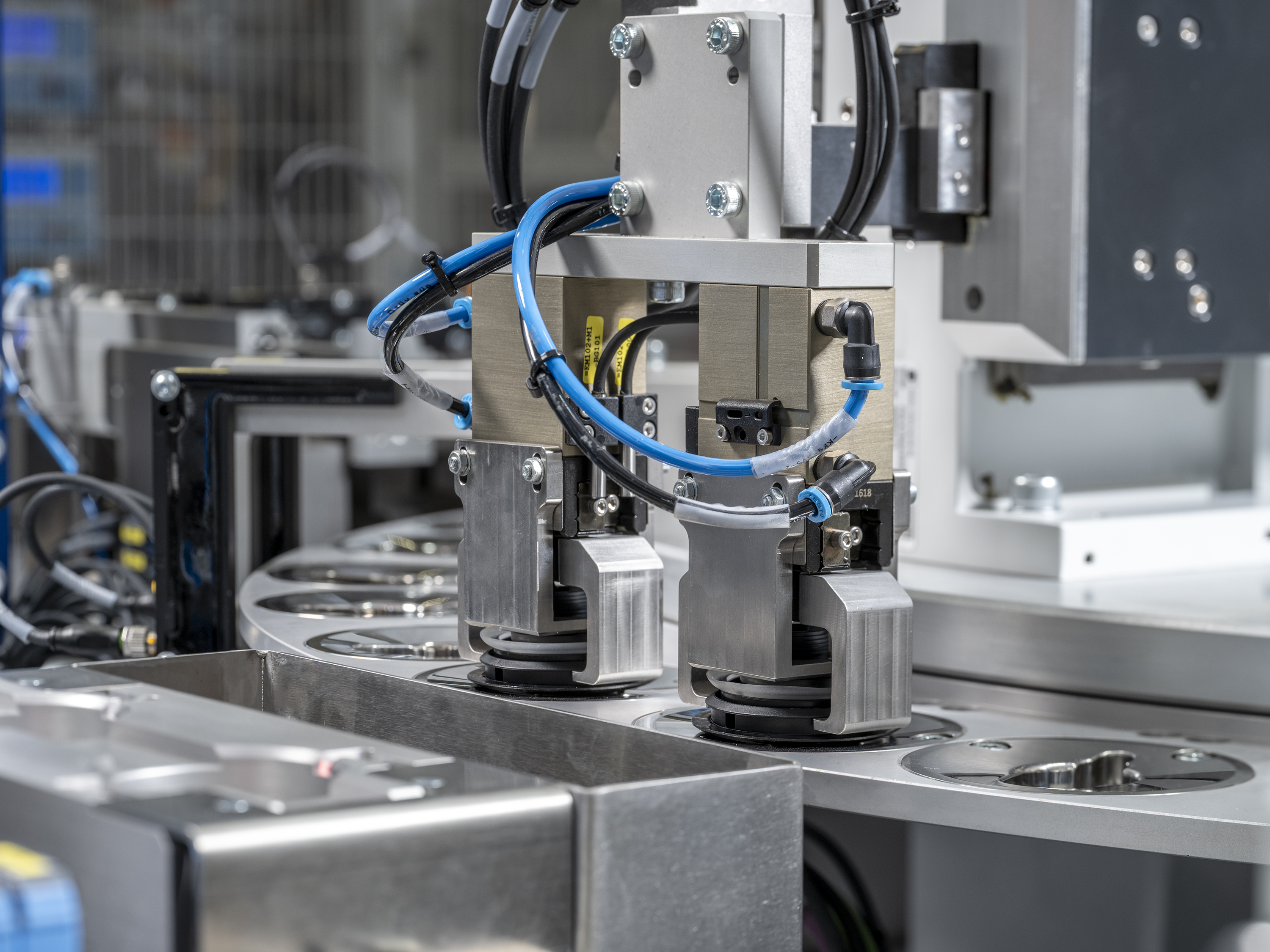
Establish a repeatable pickup and placement
Parts arriving from a feeding track must be separated and presented in a suitable orientation. A static pickup pocket can isolate a part from the movement of the parts behind it. The handling unit then needs to place it without losing the orientation required by the machine.
Gripper design depends on the shape, material and surfaces available for contact. A component may be easy to pick up but difficult to place accurately if it can twist or deform inside the gripper. The transfer and the gripper should therefore be assessed together.
Support the part for its printing method
Contact printing introduces forces at the product surface. Thin walls can deform unless the fixture provides suitable support. For dry offset, the component must rotate without slipping while its surface speed matches the blanket. Axial movement, runout and ovality can affect the image.
Inkjet avoids mechanical printing contact, but the fixture still applies holding forces. The distance between the nozzle plate and the surface must remain controlled. Recesses, taper and features near the print area can change clearance even when the nominal barrel diameter remains the same.
| Positioning issue | Possible process consequence |
|---|---|
| Part rotates or slips in its fixture | Artwork position or contact printing changes |
| Thin wall deforms under load | Surface shape changes during printing |
| Head gap varies | Inkjet droplet flight and placement change |
| Transfer arrives out of sequence | Handover conflicts with the receiving station |
Synchronize the handover
A handler and the receiving station must agree on timing and position. At higher speeds, a transfer into a moving dial is different from loading a stationary pocket. Controlled mechanical or servo motion may be needed to deliver the part within the required window.
Vision-guided handling can help identify part position and orientation. The required approach depends on output, accuracy, product variation and the motion concept. Simulation can also be used to investigate the timing between interacting movements before the physical system is completed.
Use representative parts in development
Include dimensional variation and the material condition expected in production. Freshly molded parts can still change dimension and may handle differently from conditioned parts. A transfer tested on a small set of ideal samples can overlook the variation the machine will encounter.
For an AAE discussion, share drawings, part samples, the intended print and assembly locations, and the surfaces that may be contacted. These details help establish the handling concept around the complete product.
Discuss product handling and positioning
Share your component, artwork and production requirements with AAE to discuss the next step.
Discuss your applicationRelated printing and assembly questions
- How to integrate printing and assembly in one automated system
- What can inline vision inspection check in product printing?
- Printing on cylindrical plastic parts: geometry, support and print quality