Simulation and augmented reality: better decisions before building automation
In 1777, Comte de Buffon explored probability through an experiment with needles and equally spaced lines. Repeated trials showed how different starting positions affected the outcome. Nearly two centuries later, Ivan Sutherland’s head-mounted display helped establish ways to view computer-generated environments. Both developments belong to the history behind the simulation and visualization tools available to engineers.
In automation, these tools help answer questions before equipment is built or modified. How will products behave inside a feeder? Can a robot complete its movement without interference? Where will operators stand when a new machine enters the production area?
Engineers can calculate or estimate individual movements and organize them in a displacement versus time diagram. This shows where each mechanism should be during the machine cycle and how its movement relates to other operations. For a clearly defined sequence, it provides a practical basis for reviewing timing and synchronization.
As systems become more complex, more interactions and variations need to be considered. Product arrival, orientation and handling conditions may vary between cycles, so statistical behavior becomes relevant alongside the planned movement sequence. Simulation becomes increasingly useful here: engineers can examine different conditions and repeated interactions instead of relying on a single nominal cycle. Deterministic motion calculations remain part of that work.
Which tool answers which question?
Simulation calculates how a modeled product, machine or process behaves under defined conditions. Engineers can change those conditions and examine the outcome.
Augmented reality, or AR, places digital objects or information over a view of the physical environment. Virtual reality, or VR, creates a computer-generated environment that users can explore. An operational digital twin connects a model to data from physical equipment.
| Engineering question | Relevant approach | Practical use |
|---|---|---|
| How do products settle in a bunker? | Product simulation | Examine positions and movement under defined conditions. |
| Are a robot and feeder synchronized? | Motion simulation and control testing | Review timing and the signals that permit each movement. |
| What happens when production modules are added? | System simulation | Evaluate shuttle movements and interaction with new processes. |
| How does the machine fit into the factory? | AR | Review placement, operator access and product outfeed. |
| How will operators experience a workstation? | VR | Explore operation and ergonomics before installation. |
| How does installed equipment behave? | Operational digital twin | Examine performance using equipment data. |
These approaches can be combined. The examples below illustrate applications and demonstrations, without implying measured customer results.
Product behavior: syringes and feeding systems
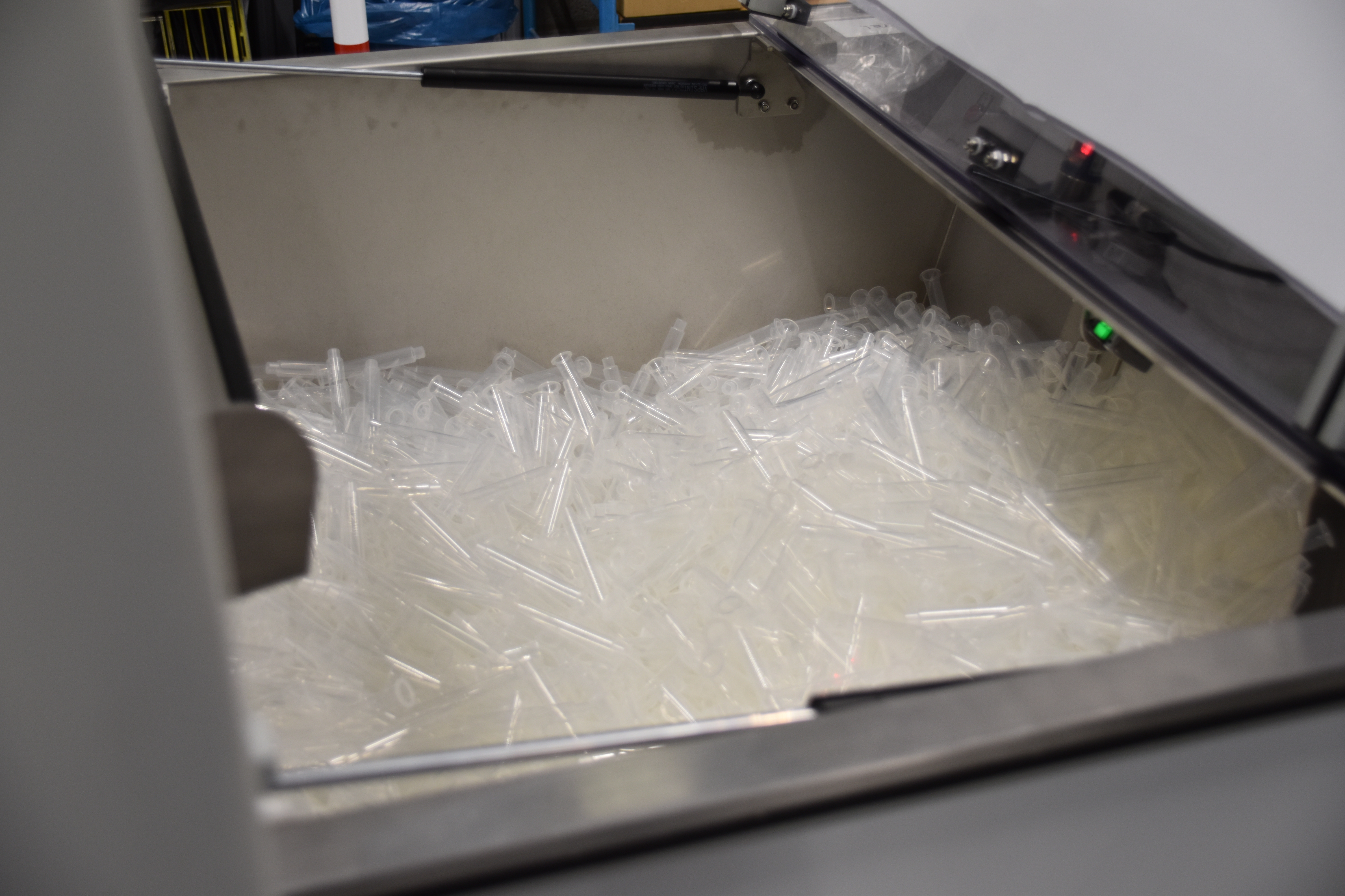
Consider a bunker filled with plastic syringes. The engineering question is whether the products fit and how they behave as they enter the container.
The simulation starts with a model that represents the syringe dimensions. Mass, gravity and initial velocity influence the result. Engineers can observe the syringes as they fall and inspect where individual products settle. A transparent view of the bunker reveals positions that would otherwise remain hidden.
A lightweight model reduces the processing effort required for these calculations. The simulation must then be checked against real conditions before its results support design decisions.
The same approach can help examine a flexible feeder with a robot and vision system. New products can be included to explore their effect on the proposed operation and its interaction with the production process.
Product characteristics determine what needs investigation. Springs can interlock, conical parts can nest together, and uneven mass distribution can cause parts to tilt during transport. Soft plastics may deform under pressure, while freshly molded products can behave differently after storage. These characteristics help define the behavior that engineers need to represent and evaluate.
Robot movements and control software
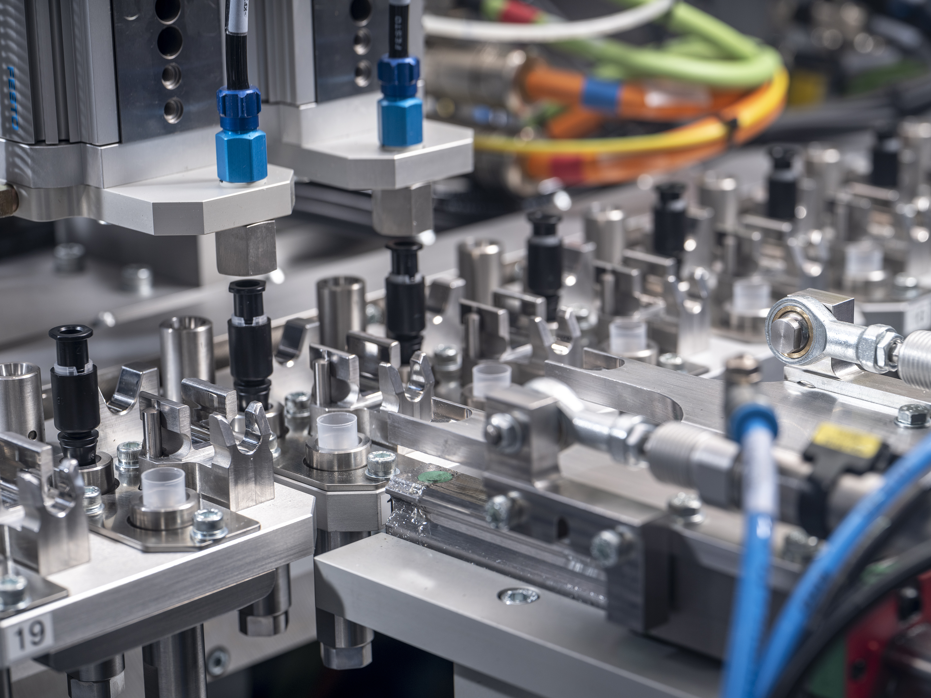
A more detailed example concerns ring-shaped products that travel along a linear track into a positioning unit. The unit separates the products and presents them to a SCARA robot.
The robot gripper enters the mechanism to collect a part. During that movement, the mechanism must remain stationary. A “Gripper down / locked” signal represents this condition. A separate “Gripper closed” signal confirms the gripping state, while another signal establishes whether the receiving assembly system is in position.
Simulation allows engineers to review the movements and their timing together. They can examine the complete transfer sequence, including the interaction between the gripper, positioning mechanism and receiving assembly system.
The investigation can also include control software. Engineers define how motors, actuators and other components behave, then connect the model to a programmable logic controller, or PLC. The controller sends commands, and the model returns simulated responses.
This supports software development before the corresponding hardware is available. It can also support virtual commissioning and checks of interaction with adjacent processes. Its value depends on the modeled behavior and signals representing the functions under test.
Line expansion and production flow
Simulation remains useful when an automation concept changes.
For example, a flexible manufacturing system can be extended with a one-meter track segment and two additional ultrasonic welding units. The shuttles receive revised motion profiles to accommodate the configuration. Virtual testing allows engineers to calculate and animate their movements before introducing the additional processes.
The surrounding logistics can also be examined. A dimensionally accurate facility model can include automated guided vehicles, machinery and available floor space. Engineers can review routes and interfaces between manufacturing equipment and warehousing.
For a production process with several manual assembly operations, a virtual representation can show workstation locations and product routing. Production data and efficiency indicators can help identify potential bottlenecks before selecting the next automation step.
There is an investment consideration alongside these technical opportunities. Flexible manufacturing introduces cost and complexity, including planning effort and staff training. Simulation helps evaluate a configuration; those organizational requirements still belong in the decision.
Augmented reality on the factory floor
AR is particularly useful when the physical surroundings form part of the engineering question.
A tablet application can display a proposed manufacturing system with robots and handling units in the existing production area. Users can inspect the arrangement and select components for a more detailed view.
| Application | What AR makes visible | Practical purpose |
|---|---|---|
| Machine placement | The proposed machine in its surroundings | Review its relationship with the production area. |
| Operator access | Access points and operator positions | Examine how staff approach and operate the equipment. |
| Product outfeed | Where completed products leave the machine | Review the connection to surrounding logistics. |
| Design discussion | Movements and selected internal components | Explain how mechanisms operate and interact. |
| Maintenance | Drawings, replacement parts and instructions | Identify the component and task being discussed. |
| Remote support | The technician’s view with expert annotations | Direct attention to the exact feature requiring examination. |
| Operating information | Robot temperature, load profile or axis speeds | Compare operation with defined parameters. |
During remote support, an expert can annotate what the technician sees. A headset also keeps the technician’s hands available for the task.
VR offers a related opportunity before installation. Operators can explore a virtual assembly position, review ergonomics and become familiar with its operation.
These applications require preparation. CAD geometry needs conversion and optimization for the intended display. Accurate movements, interactive views and technical information require additional development.
Simulation and AR are useful when they make a specific decision testable or easier to inspect. Start with the uncertainty: product handling, synchronized movements, line expansion or operator access. Then define what the model needs to represent.
Share your automation question with AAE. Product drawings, an initial layout or a proposed movement sequence can help make the discussion concrete.