How to choose feeding technology for automated assembly
A part can move quickly through a feeder and still arrive incorrectly positioned for assembly. Selecting feeding technology therefore starts with the product: its shape, material, natural orientation and sensitivity to handling. Required output, product variation and the transfer into the assembly machine determine which combination of equipment is suitable.
The selection also needs to account for what happens during extended operation. Parts may repeatedly circulate or become trapped, and noise can influence the design of the installation. Reliable feeding means delivering usable parts consistently, with acceptable handling conditions throughout the system.
Which feeder does what?
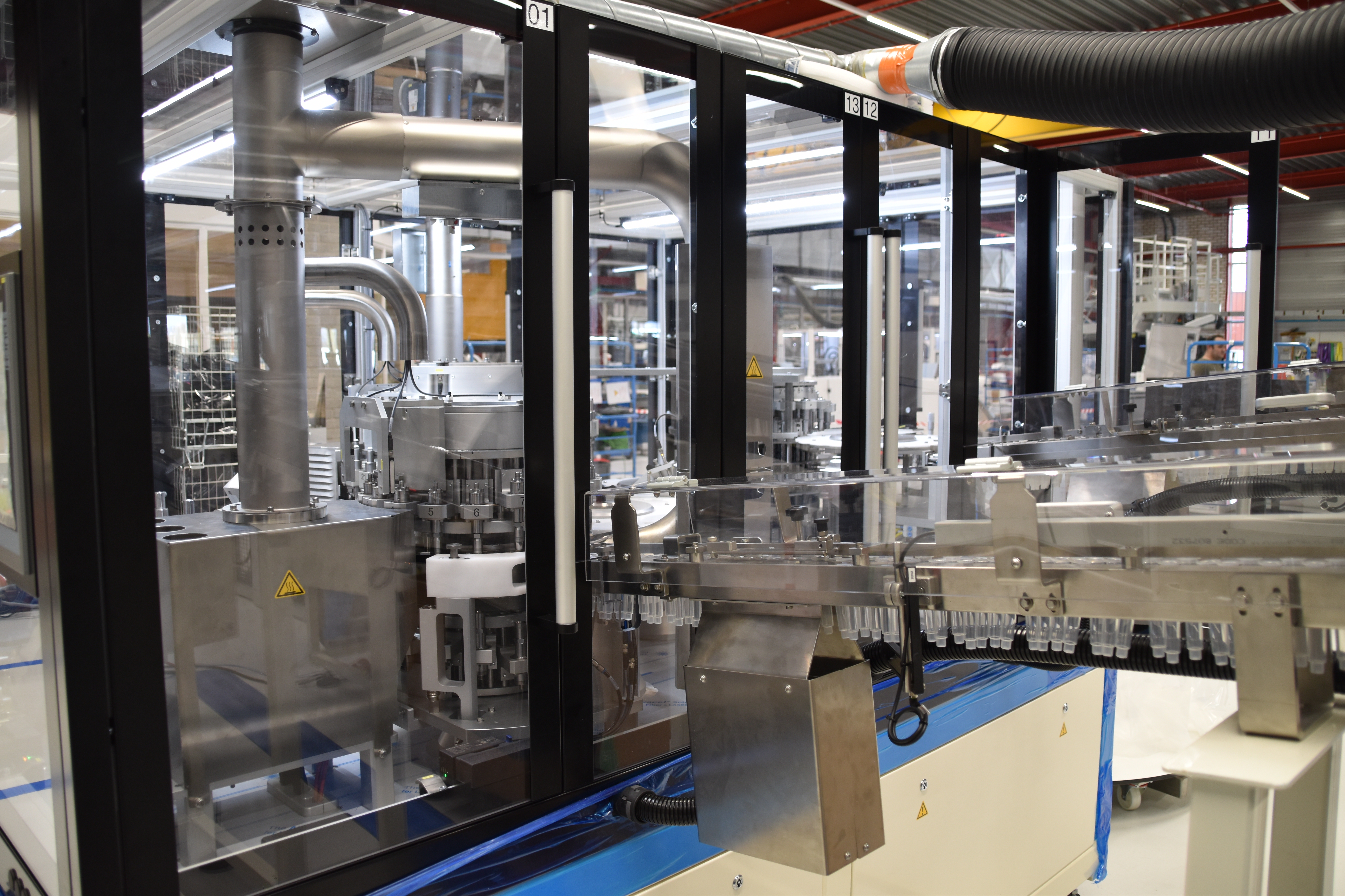
Feeding systems combine several functions: bulk storage, separation into individual parts, orientation, transport and loading. The following options address different stages and are often used together.
| Technology | Function and operating principle | Main selection consideration |
|---|---|---|
| Step or bunker feeder | An elevator mechanism takes small batches from bulk storage and supplies the next stage. | Provides bulk capacity and initial separation. Batch quantities can vary, so further control of the supply may be necessary. |
| Vibrating hopper | Supplies controlled quantities, commonly upstream of a bowl or centrifugal feeder. | Regulates the amount entering the next stage and extends operation between refills. |
| Vibratory bowl feeder | Vibration moves parts along an internal spiral track. Guides select and orient them. | Geometry and natural orientation influence performance. Overloading, jamming and repeated recirculation need attention. |
| Centrifugal or rotary feeder | A rotating disc or rotor moves parts outward toward the surrounding track. | Often offers higher output than a vibrating bowl, but achievable speed depends on the actual part and feeding conditions. |
| Carpet feeder | Transports components along tracks or channels lined with suitable soft or brushed material. | An option for fragile components when step, bowl or centrifugal feeding is unsuitable. |
| Vibratory linear track | Moves oriented parts toward the machine through controlled vibration. | Provides transport and buffering; the final pickup position still needs appropriate control. |
| Air track | Directed airflow propels parts along a guided track. | Particularly relevant for lightweight parts with suitable geometry. Air supply and consumption form part of the selection. |
| Gravity track or belt conveyor | Transfers parts toward the next process without a vibratory transport drive. | Must preserve the required orientation and suit the receiving arrangement. |
| Flexible feeder with vision and robot | Presents separated parts to a camera, which identifies pickable components and guides a robot. | Can combine separation, orientation and loading. Robot movements must fit the machine cycle. |
The product determines the handling challenge
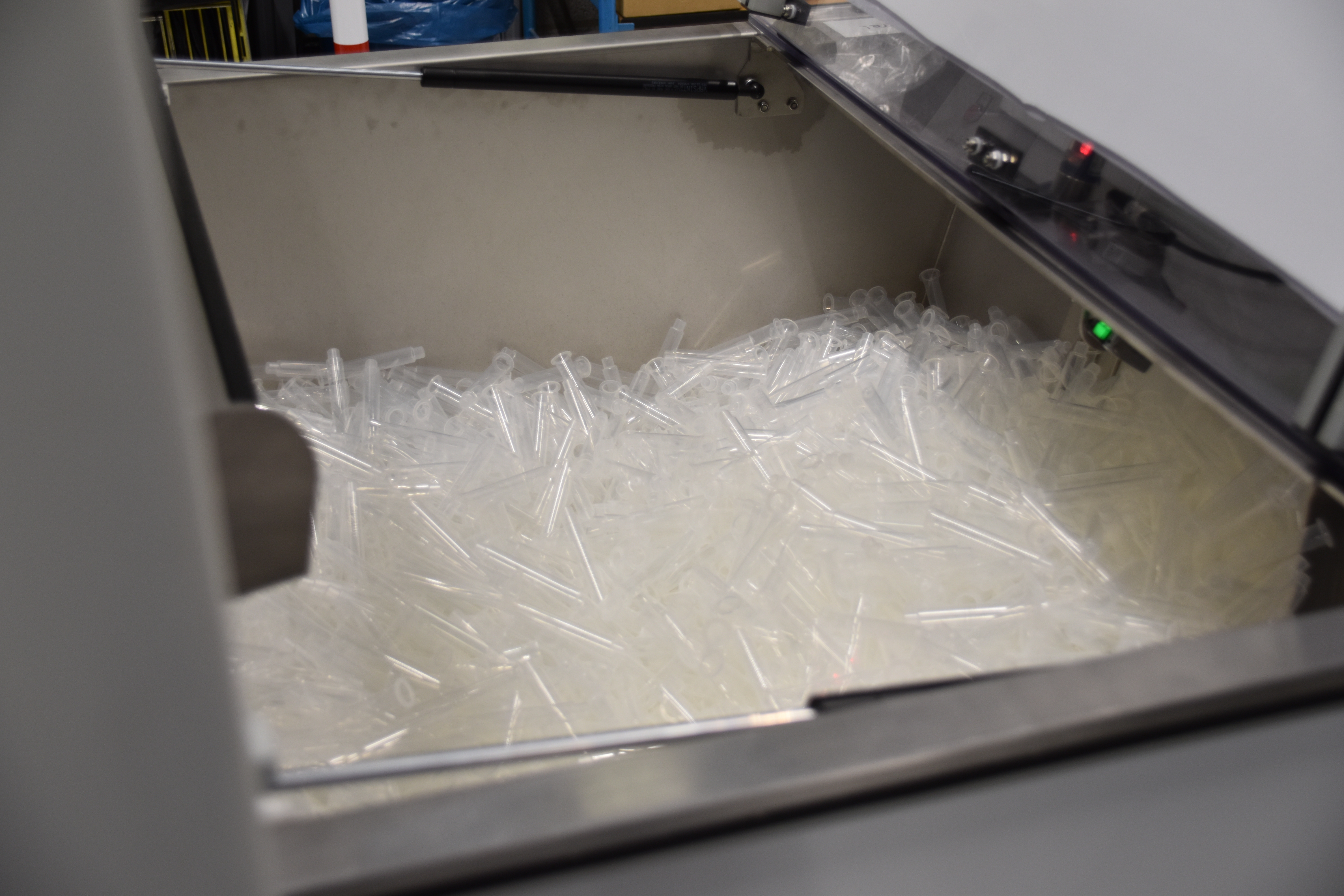
Geometry affects whether components separate freely or remain connected. Springs can interlock, while hollow or conical parts can fit inside one another. These behaviors need attention before the feeder concept is selected.
Material adds another variable. Soft plastic parts can deform under pressure, and components at the bottom of a bulk container carry the weight of those above them. Freshly molded products may also behave differently from stored parts. Feeding trials should therefore reflect the condition in which products will actually enter production.
Natural orientation can help. A rectangular component may usually rest on its larger face but need to enter assembly upright. A bowl track can accept the stable orientation, remove incorrectly aligned parts and then rotate the accepted components through 90 degrees with a guide. The final assembly orientation does not have to be established immediately after separation.
Weight distribution matters throughout this sequence. An offset center of gravity can make a component tilt during transport, even after it has left the orientation stage correctly.
For some medical products, particle-generation requirements can exclude methods that allow components to rub against one another. These restrictions belong in the initial technology selection.
Air tracks and vibratory tracks
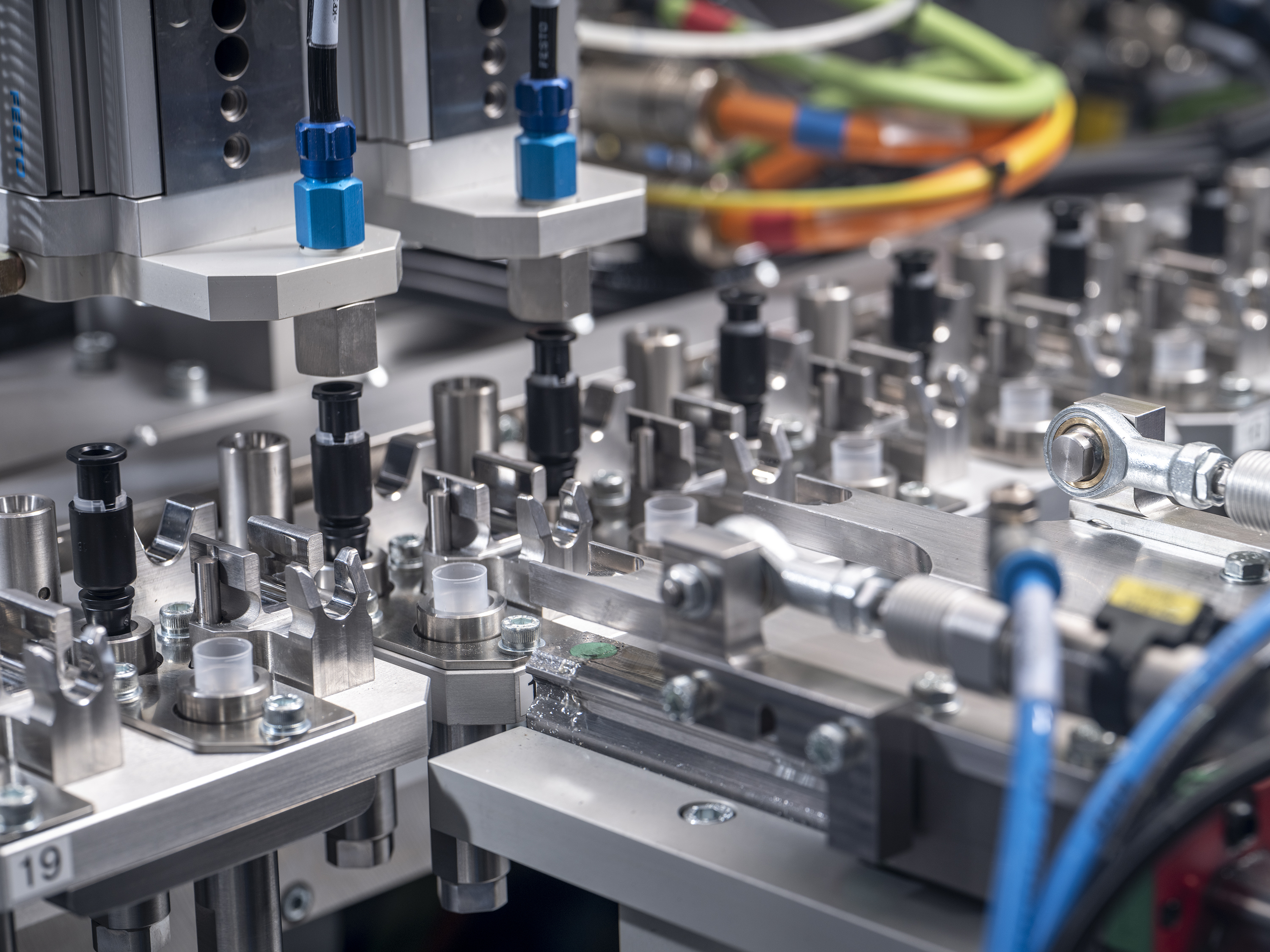
A vibratory track advances components through repeated mechanical movement. An air track uses airflow through small, angled openings to lift and propel suitable parts along a stationary track. Depending on the design, the air can come from a compressed-air supply or an electric blower.
Air tracks are particularly useful for lightweight components with enough exposed surface area for the airflow to act on. They can reduce sliding contact and provide gentle transport over extended distances. Their suitability depends on the relationship between part geometry, weight and track design.
The upstream feeder and downstream track can use different principles. A vibratory bowl can separate and orient the parts, then deliver them to an air track for transport to the assembly machine. The air-hole size, position and angle must suit the component and required feed rate.
An air track can therefore be worth considering when transport contact or vibration is a concern. Its air requirement and operating cost should be assessed alongside the mechanical alternative; it is not automatically the better choice for heavy or irregular parts.
Parts that circulate, jam or remain behind
Repeated recirculation and physical trapping are different problems.
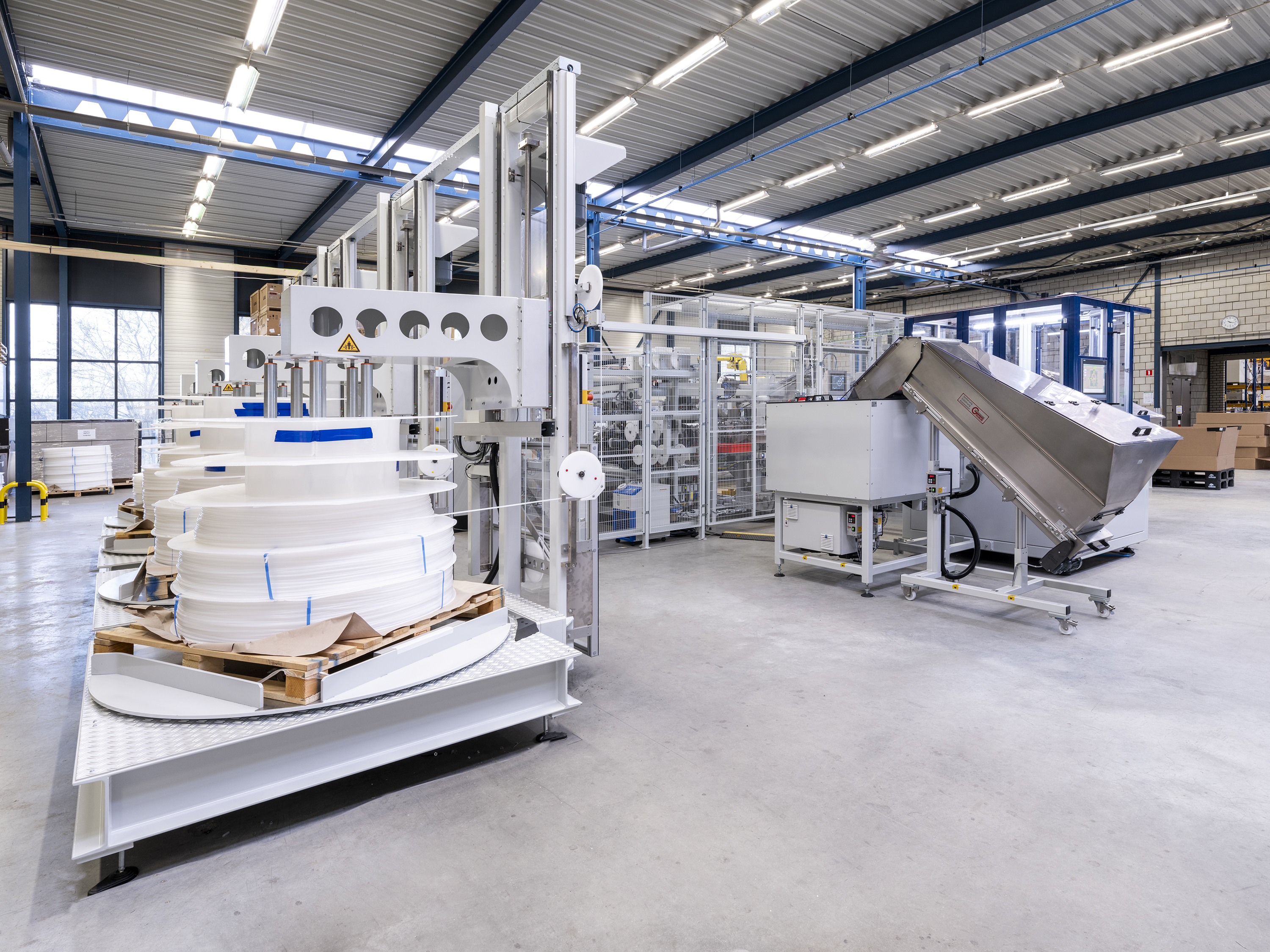
In a bowl feeder, incorrectly oriented parts can return to the bowl for another pass. Some recirculation is inherent to this method, but excessive recirculation increases repeated handling. Where the product allows it, accepting more than one initial orientation and correcting the orientation downstream can reduce the number of return passes.
Physical trapping is more persistent: a component becomes caught in a gap and does not leave through the normal feeding route. In certain bowl designs with loose or rotating centers, parts can become trapped between the center and the bowl. Residual components may remain even after the feeder has been run empty. Fixed-center designs can avoid this particular gap and permit complete emptying. This is a design-specific distinction, not a characteristic of every vibratory feeder.
The practical acceptance question is therefore broader than whether parts emerge at the required rate: can the system also be emptied reliably, and can retained parts be found and removed? That question should be considered alongside the amount of recirculation and the condition of the components after feeding.
Noise belongs in the equipment specification
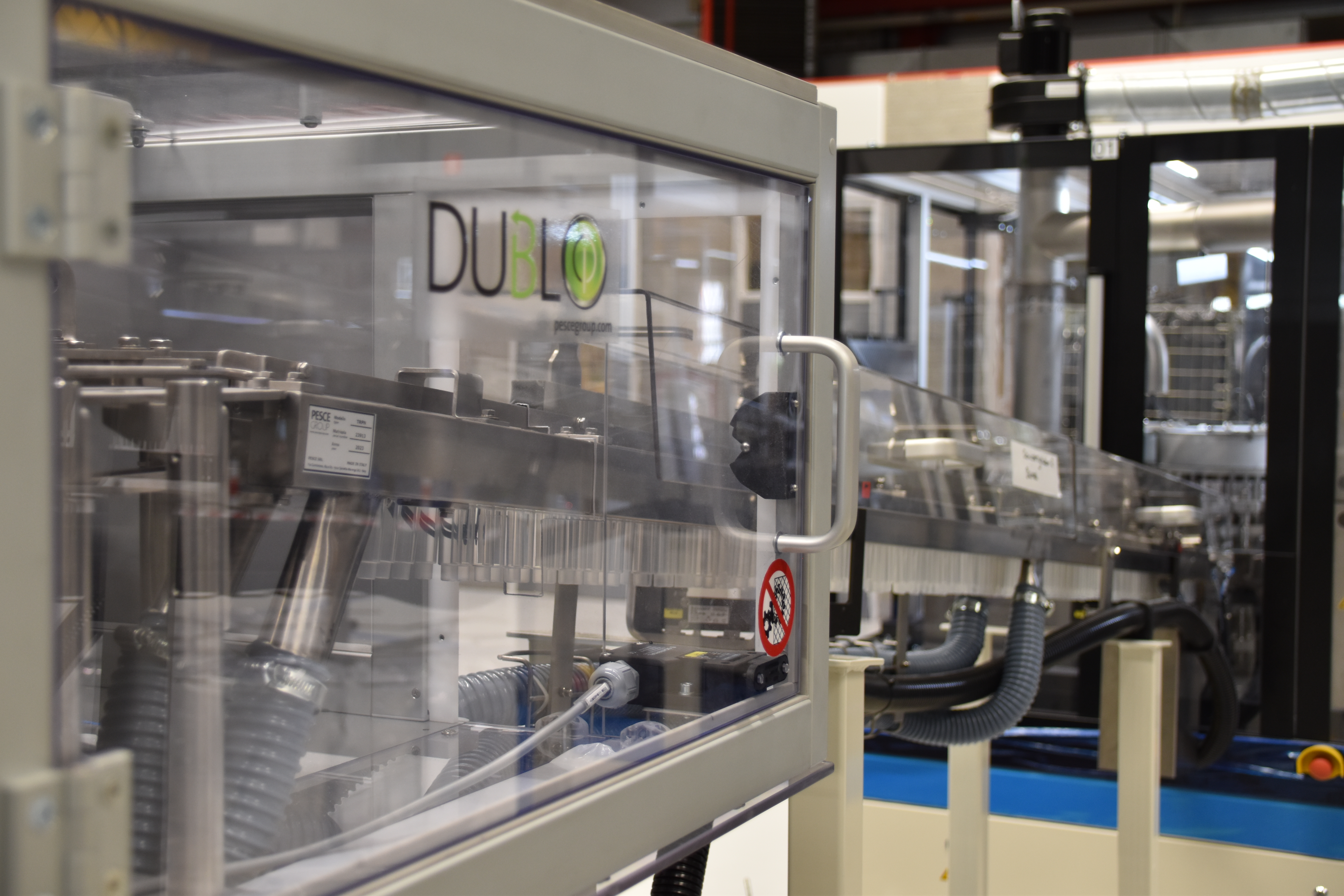
Noise can arise from the feeder drive and structure, as well as from components striking the track and one another. Part material and weight affect the result. Increasing vibration amplitude to obtain more output can also increase bouncing and noise.
Possible measures include suitable track coatings, controlled bowl loading and acoustic enclosures. Coatings must match the component and application; an enclosure also needs to allow the required access for refilling and intervention.
Air tracks can reduce transport noise compared with vibratory tracks for suitable applications. However, selection should compare the complete operating installation, including its air supply, at the required production rate. A sensible acceptance requirement is to evaluate noise with actual parts and normal operating conditions, alongside throughput and handling quality.
From feeder output to reliable machine loading
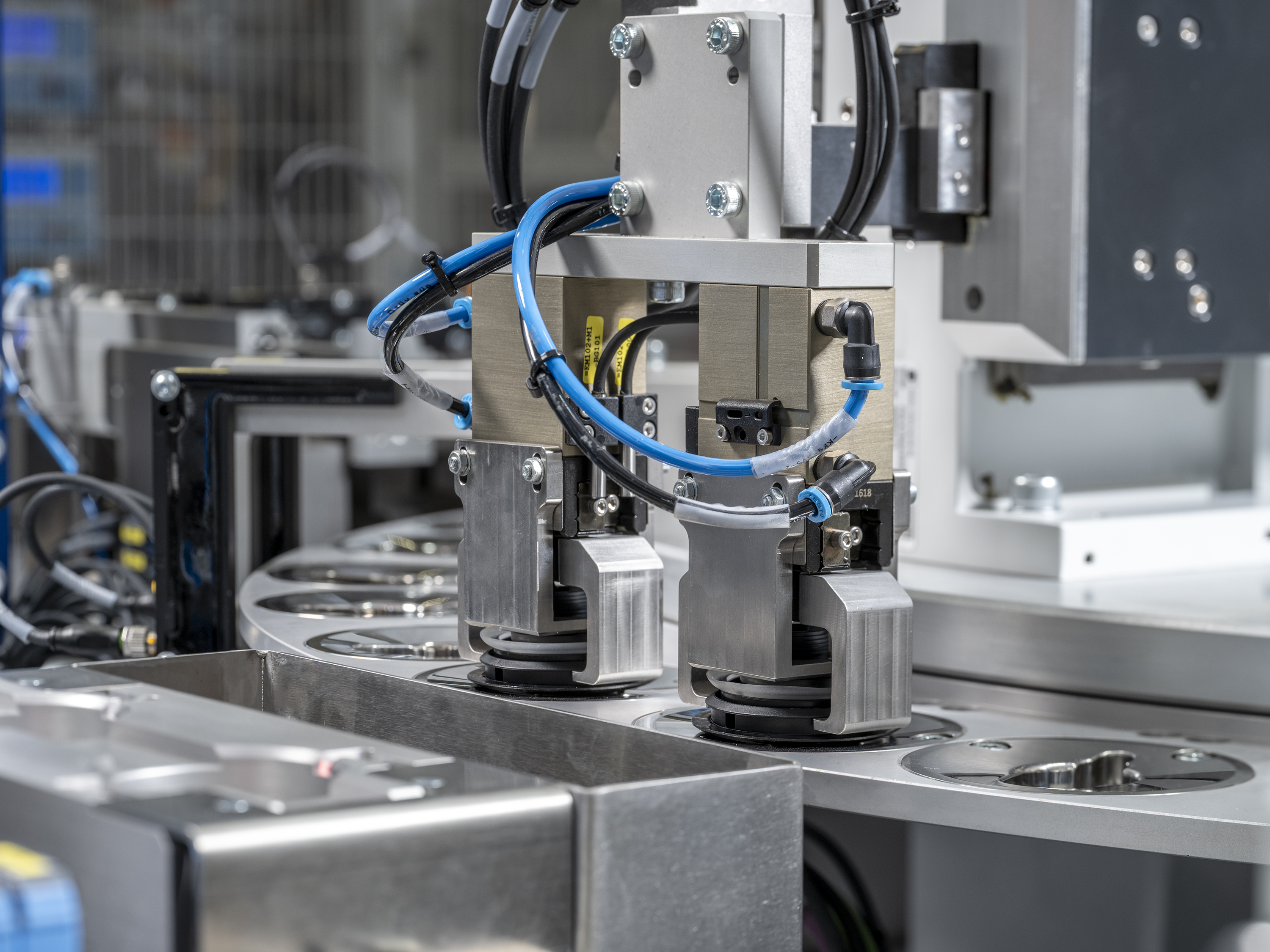
The last transfer deserves as much attention as bulk separation. A linear track can deliver oriented components, but vibration or pressure from following parts can disturb the component at the pickup position.
A dead nest provides a stationary pocket for the leading component while a clamp restrains the parts behind it. The handling unit can then collect the isolated part without interference from the queue.
Pneumatic systems can provide a simple, economical transfer. Greater speed or positioning demands may require cam-driven, servo-controlled or robotic handling. Gripper design, maintenance, investment cost and the required motion profile also influence the choice.
Continuous-motion assembly introduces a different condition because the receiving position keeps moving. A feed screw, also called a worm drive, can establish controlled spacing and timing before parts enter the rotating assembly system. For syringe plungers, it can provide a more defined position than the upstream vibrating track.
Vision-guided robots offer another approach. A camera locates a pickable part and guides the robot. Where necessary, a second camera inspects the component in the gripper so that the robot can correct its orientation before placement. Simulation can help examine the timing and interaction between these movements and the receiving machine.
AAE develops printing and assembly systems in which these transfers form part of the overall machine design. The final choice should follow the component through its complete journey: how it separates, how it travels, whether it can remain trapped, and how it enters the machine.
Share your feeding challenge with AAE. Product drawings or samples, required output, product variants and handling restrictions provide a useful starting point. Include expectations for noise and complete emptying in that discussion.